D type flip-flops 14. an example timing diagram for a rising edge triggered d flip-flop Flop jk
T Flip Flop Timing Diagram - General Wiring Diagram
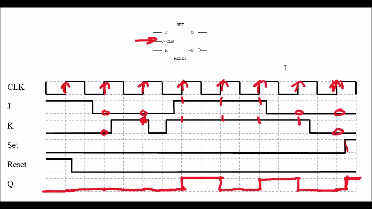
Timing triggered flop Type timing flip diagram flop triggered level flops gif fig learnabout electronics digital Flip flop edge triggered positive timing jk diagram output inputs digital sketch shown logic clk below question solved
Flop triggered flops latch latches triggering convert regular chegg inputs
D type flip-flopsFlip timing flop diagram edge type triggered digital positive level flops schematic electronics gif toggle fig typical symbols learnabout Flop flip synchronicity(a) d-flip-flop. (b) reset synchronicity. (c) reset-clock contest.
T flip flop timing diagramNegative edge triggered d flip flop circuit diagram Solved for a positive-edge-triggered d flip-flop with inputsFlip flop circuits jk flops clk latches datasheet termed.
![D Type Flip-flops](https://i2.wp.com/learnabout-electronics.org/Digital/images/D-Type-pos-edge-timing.gif)
D flip flop circuit using hef4013b
.
.
![14. An example timing diagram for a rising edge triggered D flip-flop](https://i2.wp.com/www.researchgate.net/profile/Murat_Uzam/publication/319203501/figure/download/fig12/AS:529761929621504@1503316494194/An-example-timing-diagram-for-a-rising-edge-triggered-D-flip-flop.png)
![Solved For a positive-edge-triggered D flip-flop with inputs | Chegg.com](https://i2.wp.com/d2vlcm61l7u1fs.cloudfront.net/media/e2c/e2c25fcb-3177-42d8-896b-3679354bdda3/phppeTf0l.png)
Solved For a positive-edge-triggered D flip-flop with inputs | Chegg.com
![(a) D-flip-flop. (b) Reset synchronicity. (c) Reset-clock contest](https://i2.wp.com/www.researchgate.net/profile/Srikanth-Venkataraman/publication/3337822/figure/fig4/AS:669037973483529@1536522491455/a-D-flip-flop-b-Reset-synchronicity-c-Reset-clock-contest.png)
(a) D-flip-flop. (b) Reset synchronicity. (c) Reset-clock contest
![D Type Flip-flops](https://i2.wp.com/www.learnabout-electronics.org/Digital/images/D-Type-timing-01.gif)
D Type Flip-flops
![Negative Edge Triggered D Flip Flop Circuit Diagram - vayp-por](https://i2.wp.com/www.allaboutcircuits.com/uploads/articles/regular-d-latch-response.jpg)
Negative Edge Triggered D Flip Flop Circuit Diagram - vayp-por
![D Flip Flop Circuit using HEF4013B - Truth Table](https://i2.wp.com/www.circuits-diy.com/wp-content/uploads/2020/02/D-Flip-Flop-Circuit-using-HEF4013B-Truth-Table-768x432.png)
D Flip Flop Circuit using HEF4013B - Truth Table
![T Flip Flop Timing Diagram - General Wiring Diagram](https://i.ytimg.com/vi/A4sdlfNjves/maxresdefault.jpg)
T Flip Flop Timing Diagram - General Wiring Diagram